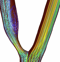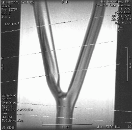
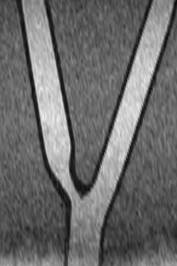
Glass phantom with PC-MR slices and CT slice
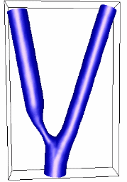
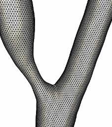
Reconstructed model and finite element grid
In vitro study using a flow-through phantom of the carotid bifurcation with 65% stenosis in the internal carotid artery. Idealized geometry and steady flow conditions. Geometry reconstructed from a CT scan of the glass phantom, using tubular deformable models and surface merging algorithms. Flow velocity measurements obtained using phase-contrast magnetic resonance (PC-MR) at five slice locations. Velocity boundary conditions imposed using parabolic profiles corresponding to the flow rates measured at the most proximal and most distal PC-MR slices. Intermediate slice locations used for comparison with computed velocity profiles. The error in the reconstructed geometry is less than 2%.


Glass phantom with PC-MR slices and CT slice


Reconstructed model and finite element grid
The velocity profiles computed by the finite element model are in good agreement with the profiles measured with PC-MR at intermediate slice locations. Note that this comparison can be greately improved if the CFD results are interpolated to a regular grid with the same size as the pixels of the PC-MR images.
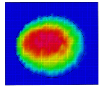
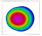
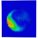
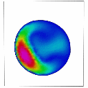
PC-MR and CFD velocity profiles at intermediate slice locations
Visualizations of the flow patterns show a recirculation region distal of the stenosis, a high speed jet near the outer wall of the internal carotid artery, and increased wall shear stresses in the region of the stenosis.
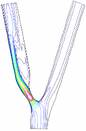
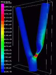
Velocity contours, and wall shear stress
The computed flow pattern agrees with particle traces obtained in the in vitro model.
